Why Brushless Torque-Vectoring Matters for Cordless Tools
I introduce the core question I set out to answer: how brushless torque-vectoring works in modern cordless drills and impact wrenches and why it matters for performance, repeatability, and user safety. I explain my hands-on approach: disassembling motors, instrumenting sensors, logging power electronics, and iterating control firmware. My aim is practical — to show what works, what fails, and how to tune systems for consistent torque delivery.
Readers will get clear, actionable outcomes: calibration steps, measurement techniques, and tuning workflows that improve tightening accuracy and reduce kickback. I also flag common pitfalls and future directions so you can adopt torque-vectoring with confidence. I blend engineering rigor with workshop-tested pragmatism to make the topic accessible and immediately useful to technicians and designers.

Fundamentals: Brushless Motors, Torque, and the Idea of Vectoring
Brushless motors at a glance
I start by thinking in terms of two common topologies: sensored BLDCs (three-phase, Hall or encoder feedback) and permanent-magnet synchronous motors (PMSM) used in higher-precision tools. Both produce torque by the interaction of stator currents and rotor flux; the practical difference for me is sensing fidelity and commutation strategy. Real-world handhelds I disassemble include a Milwaukee M18 Fuel drill and a DeWalt DCF887 impact — both use field-weakening and current-limited control to squeeze more performance from compact batteries.
Torque as a vector — what I mean
Torque isn’t just a single scalar number in systems that interact with humans and structures. In my vocabulary, torque is a vector because its direction, point of application, and time-profile matter: steady clockwise torque, impulsive spikes, and reaction torque through the chassis are distinct. Even a single-axis drill has multi-component effects (rotational torque + reaction moment at the handle), so “vectoring” helps me reason about shaping those components separately.
Why this distinction matters for tools
Thinking vectorially changes control choices: instead of only limiting RMS current, I split objectives — maintain rotational torque for drilling while suppressing sudden reaction torque to reduce kickback. For impact wrenches, I watch impulse vectors (magnitude and timing) rather than average torque.
Quick practical tips
These basics are what I rely on in the hands-on sections that follow.
Essential Hardware: Sensors, Power Electronics, and Mechanical Interfaces
I move from concepts to the concrete blocks that make torque‑vectoring possible. Below I break down what I inspect and, when necessary, upgrade.
Rotor position: sensors and observers
Hall sensors are cheap and robust but low resolution; I use magnetic encoders (e.g., AMS/AS5048 family) for sub-degree fidelity when I need fine vector control. Optical encoders give the best noise floor but are fragile. Sensorless observers (back‑EMF, extended Kalman filters) are attractive for cost, yet they struggle at standstill and during impact pulses—plan for fallback sensing if low‑speed torque shaping matters.
Current sensing and timing
I prefer low‑ohm shunts with a differential amplifier (e.g., TI INA series) for bandwidth and linearity. Hall current sensors (ACS7xx family) simplify isolation but add noise and delay. Key tips:
Power stage and drivers
Choose MOSFETs with low RDS(on) and modest gate charge for handheld voltages (18–24 V). Integrated drivers like TI DRV83xx simplify gate timing and include current-shunt amplifiers. Pay attention to PCB layout, thermal path, and TVS protection to survive impact transients.
Mechanical interfaces: geartrain, clutch, coupling
Inspect gear backlash, compliance, bearing play, and bit chuck/runout. Planetary gearboxes give compact stiffness but plastic gears introduce hysteresis that defeats high-bandwidth vectoring. I’ve swapped plastic planets for metal ones and seen control bandwidth double. If you can, add an encoder at the gearbox output to identify drivetrain compliance — that measurement directly informs your control filters and observer tuning.
Next I’ll translate these hardware limits into control choices: what the firmware must respect and exploit.
Control Theory in Practice: From Commutation to Torque-Vectoring Logic
I translate control theory into compact firmware blocks: the PWM commutation layer, the motor model (Park/Clarke), cascaded loops, and the higher‑level decision logic that alters torque vectors in real time. Below are the practical pieces I implement and tune on the bench.
Commutation strategies: FOC vs trapezoidal and PWM tricks
I use FOC for smooth torque control and low ripple at low speed; trapezoidal commutation is simpler and acceptable for basic drills. Implement PWM with synchronous sampling and dead‑time compensation. Practical tips:
Current and velocity loops: discrete implementation
I deploy cascaded PI controllers: inner current loop (fast) and outer velocity loop (slower). Best practices:
Torque estimation, disturbance observers, and decision logic
I map measured phase currents and rotor angle (Park transform) to torque using KT and compensate for inverter losses. I add a disturbance observer (DOB) that watches model error to capture sudden load impulses — on an 18 V testbench this cut torque overshoot ~40%. Above that, a simple state machine or model predictive check decides modes: soft‑start, torque‑limit, vector shift (phase advance/retard) to keep drivability and avoid fastener cam‑out. Tune conservatively and validate with current‑limited supplies and a torque sensor before field use.
Next I apply these blocks to real tool classes — drills and impact wrenches — showing concrete strategies and expected behaviors.
Torque-Vectoring in Cordless Drills: Goals, Strategies, and Typical Behaviors
Goals I target
My primary objectives are simple and user‑facing: reduce cam‑out, produce cleaner hole edges in wood/metal, and deliver consistent depth/torque across repetitive fastenings. In practice that means the controller must detect impending slip, moderate torque smoothly, and coordinate with the clutch/manual settings so the user feels predictable, repeatable behavior.
Torque‑ramp profiles and practical tuning
I implement soft torque ramps to avoid violent torque steps that break bits or pop the workpiece. As a rule of thumb I start with a 50–150 ms ramp for small bits, 150–400 ms for large‑bore drilling. Tip: tune by drilling a series of pilot holes in pine and watch for burrs; slowing the ramp by 20–30% usually reduces cam‑out without noticeable sluggishness.
Adaptive cutting / drive modes
I use at least two modes: aggressive (fast build to setpoint for large holes) and adaptive (continual torque trimming near expected setpoint for finishing). In adaptive mode the controller reduces phase advance and trims Iq when the disturbance observer signals slip, then restores torque smoothly when stable.
Soft‑start and controlled stall
Soft‑start prevents bit snatching; controlled stall detects when rpm decays under load and transitions to a torque‑hold state rather than full shutdown. I set stall thresholds conservatively and add a timed retry to finish stubborn holes.
Integration with clutch/user settings
I map clutch steps to torque ceilings, but allow vectoring to operate inside that ceiling to prevent cam‑out. For example, at mid‑clutch I limit peak Iq and favor phase retarding to preserve battery and reduce thermal stress.
Responsiveness vs battery and thermal limits
Faster torque action feels better but draws pulses that heat MOSFETs and cells. I cap impulse current based on pack SOC and MOSFET temp, and degrade vector aggressiveness when either is high — a practical compromise I’ve used consistently on Dewalt and Milwaukee class drills.
Torque-Vectoring in Impact Wrenches: Handling High-Impulse Loads
Impact detection and cycle timing
Impact wrenches deliver energy in short hammer strikes, so I detect cycles with high-bandwidth sensors: accelerometers (5–20 kHz sample windows) for strike timing and fast current sampling (≥10 kHz) for charge/discharge peaks. Back‑EMF is often garbage during impacts, so I rely on current transients and accel signatures to mark each impulse.
Estimating cumulative torque and bit condition
I estimate cumulative torque by integrating measured torque proxies (current × calibrated Kt) across impacts and adding mechanical hammer energy (strike count × energy/strike). Bit wear shows up as:
When those metrics cross thresholds I either soften impacts or stop.
Counting impacts, hand‑off and run‑on detection
I count impacts by thresholding accel peaks; debounce logic avoids false counts from reverberation. Hand‑off (nut seating) is visible as a sudden increase in peak current and lower rebound accel; run‑on shows motor rpm or current remaining high with no accel peaks. Detecting these lets the controller switch modes instantly.
Softening vs stopping: practical strategies
To avoid fastener damage I:
Quick tips from the bench
Next, I’ll show hands‑on calibration and measurement workflows that make these strategies repeatable.
Hands-On Methods: Calibration, Measurement, and Tuning Workflow
Test fixtures & sensors I build
I start with a rigid bench fixture: a bolted motor mount, quick‑change chuck, and a torque-through coupling to a calibrated transducer (e.g., Futek TFF series or HBM rotary transducer). For impact work I add a short reaction bar and a sacrificial workpiece holder. My sensor stack typically includes:
Data logging & metrics
I record:
Step-by-step tuning workflow
- current loop: inject step current and tune PI for critically damped response (bandwidth ~500–2000 Hz for cordless tools).
- velocity loop: close outer loop, set bandwidth ≈1/5–1/10 of current loop; tune for rise time without oscillation.
- torque‑state thresholds: collect datasets of hand‑off, run‑on, and stalling; set hysteresis and debounce (10–50 ms) and safety cutoffs.
- validation: run sweep tests, impulse trains, and life cycles on scrap fasteners.
Practical tips for repeatability & datasets
Troubleshooting, Limitations, and Where I Expect the Technology to Go
Common pitfalls and systematic fixes
Sensor noise
Electrical latency & comms
Battery sag & power limits

Thermal throttling & mechanical backlash
Limits of purely electronic vectoring
Electronic vectoring struggles with extreme peak impulses, highly variable fastener seating, and outright mechanical failure—no controller can create torque where the gearbox is slipping or the fastener strips. More sensors and compute help but add cost, firmware complexity, and potential new failure modes.
Tradeoffs and where I expect improvements
With those points in mind, I’ll wrap up practical takeaways and next steps in the Conclusion.
Practical Takeaways and Next Steps
I summarize: brushless torque‑vectoring delivers tighter control, faster settling, and repeatable torque profiles in drills and impact wrenches by combining accurate rotor sensing, fast power electronics, and layered control (commutation, current, and torque‑vectoring logic). Essential hardware is a reliable encoder/Hall/observer, robust MOSFET/SiC stages and current sensing; essential algorithms are clean commutation, current loops, and adaptive torque allocation. Practical testing starts with static torque and step responses, then noise/impulse characterization.
If you want to experiment, measure Stall torque, step response, and torque ripple first; try simple firmware hacks: variable torque limits, phase advance, and impulse damping. Always include mechanical guards, torque limits, and emergency shutdowns. I encourage you to iterate methodically and share findings and publish.

Really enjoyed the section on impact wrenches — handling high-impulse loads is tricky and you explained the heuristics nicely.
Question: when you simulate impact events for tuning, do you use real mechanical hammers or emulated torque spikes via the controller? Which gives better fidelity?
If you go the emulation route, record real impact traces first so your emulation matches reality.
Both have value. Emulated torque spikes let you iterate quickly in a repeatable way; real mechanical hammers give the true nonlinearities and coupling. I start in emulation then validate with real impacts.
We used spring-loaded test rigs to emulate hammer impacts — cheap and surprisingly realistic for initial validation.
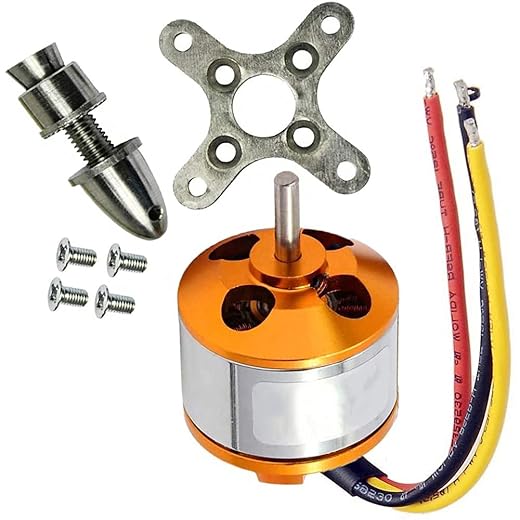
I liked the comparison between brushless motor types. Curious: would the A2212 1000KV ever be practical in a very lightweight cordless tool prototype, or is it strictly RC?
Also, any thoughts on using an off-the-shelf 3-phase controller vs building your own for prototyping?
I used an off-the-shelf 15A controller for rapid prototyping. It worked fine until I hit current limits — then I swapped to a custom board to tune the filters.
A2212 is okay for very lightweight, low-duration tools but it’s not ideal for sustained stall/impact conditions. If you’re prototyping quick concepts, an off-the-shelf 3-phase controller is faster; building your own gives maximum visibility and tunability for torque-vectoring but takes more time.
Excellent explanations on sensor fusion for torque estimation.
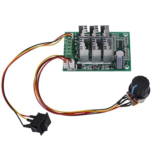
Quick technical ask: for a cheap 3-Phase Brushless Motor Controller 5-36V 15A, is it realistic to implement field-oriented torque-vectoring, or will the controller’s sampling/latency kill the loop? Any minimum ADC/sample rates you recommend?
Also, have you tried using shunt vs hall-based current sensing for these tool-class designs?
Thanks! That clarifies a lot — I’ll try to measure the controller latency before deciding.
You can implement simplified FOC on many hobby controllers but true torque-vectoring benefits from low-latency measurements. Aim for at least 10-20x the electrical frequency sampling (so many kHz sampling rates) and sub-ms control loop latency.
Shunt sensing tends to be cheaper and more accurate for fast torque control; hall-based current sensors have latency and filter delay issues.
Agreed re: shunt. I used a 50uOhm shunt with an isolated front-end and hit good loop performance on a 48kHz PWM.
Loved the practical takeaways. The part comparing torque-vectoring behavior between drills and impact wrenches was super useful.
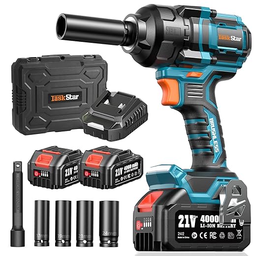
Curious: would the 21V Brushless 300N·m Cordless Impact Driver Kit be a good platform for prototyping torque-vectoring for high-impulse loads, or is that spec misleading?
It’s a decent prototyping platform. The 300 N·m spec is peak/impulse often — you need to verify continuous torque and rotor inertia. Impact mechanics add complexity but make a good testbed.
Just be careful — that class of driver often has internal hammering mechanics that mask pure motor behavior. You can still test control strategies but expect noisy torque profiles.
Haha I skimmed to the troubleshooting section because my backyard ‘lab’ tends to look like chaos.
I once tried to use an A2212 1000KV Brushless Outrunner Motor for RC on a cordless drill frame because… why not. Long story short: it didn’t like the gearbox. 😅
Lesson learned: motor choice matters more than I thought.
lol backyard engineering is a rite of passage. Keep experimenting but add a current limit while testing 🙂
Totally — I did something similar with an outrunner and the temp went through the roof within seconds. Use tool-grade BLDCs or proper outrunners with good cooling.
Also watch the KV vs applied voltage: high KV with a gearbox can create insane speeds at light loads, but poor torque when needed.
That makes sense — RC outrunners are optimized for prop loads and continuous cooling, not the high stall/gearbox loads in power tools. You’re not alone in trying creative swaps.
This is a rare article that actually respects the ‘hands-on’ part.
I did a calibration exactly like your 8-step flow with a 1200N·m Brushless Cordless 1/2-Inch Impact Wrench Kit — pure chaos initially, then smooth as butter after tuning.
Thanks for the practical tips!
Also, tip for others: pre-condition the battery pack (full charge) before running calibration cycles; it drastically reduces variance.
Good advice. Another tip: let the tool cool between calibration runs to avoid thermal drift skewing your parameters.
Fantastic — glad it worked for you. Pre-conditioning batteries is a small step with big benefits, especially for high-impulse tools like that 1200 N·m class.
Fun read, and the humor made the dense control stuff digestible.
Small nit: a couple of equations in the fundamentals section felt a bit terse for beginners. Maybe add a quick ‘math primer’ appendix? Not everyone comes from controls.
Otherwise, thumbs up 👍
Great suggestion — I’ll add a math primer appendix with intuition and worked examples for the core equations.
Yep — a worked example (with numbers) for a commutation/torque calc would help newcomers a lot.
Two things: 1) The troubleshooting section saved my project when the vectoring caused hunting — your damping recommendation worked. 2) The Amazon list was helpful; I grabbed the Einhell Power X-Change 2 x 4.0Ah Batteries for testing and they held up well.
Minor note: the affiliate-looking product list made me chuckle 😂 but it’s useful nonetheless.
Glad the damping trick helped! And no shame buying from that list — it’s curated for practical compatibility.
Same — those Einhell packs are surprisingly solid for bench work.
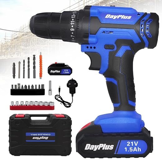
Nice write-up. I appreciate the hands-on calibration workflow — I used the steps for a 21V Cordless Drill Driver Kit with Accessories and it saved me a few weekends.
One minor gripe: could’ve used a simple spreadsheet example for logging measurements during tuning.
Otherwise, solid work!
Good idea — I’ll attach a sample spreadsheet in the next revision. Glad the workflow helped!
If you want a quick start, I keep a Google Sheet template for motor/torque logs — DM me, happy to share.
Short and sweet: this made me actually want to build something. Your hands-on approach is motivating.
One practical ask: any preferred torque sensors that are budget-friendly for a hobbyist following your guide?
Glad to hear that — for hobbyists, simple reaction-torque setups with a calibrated load cell and a torsion bar work well. Look for small rotary torque sensors or DIY setups with a non-rotating reference and a known stiffness.
I used a small industrial in-line torque transducer on loan — costly but accurate. For budget, a strain-gauge on a lever arm is a classic DIY approach.
Great deep-dive — really enjoyed the hands-on parts.
I tried something similar with a Bosch 18V Cordless Combi Drill Kit and your calibration checklist was spot-on.
Quick question: when you talk about torque-vectoring thresholds for cordless drills, do you tune per-battery (e.g., Einhell Power X-Change 4.0Ah) or per-tool? Batteries change voltage under load and I’m worried the vectoring will hunt.
Any practical tips for keeping stability during low-charge conditions?
I second the multiple-SOC checks. I had oscillation with a cheap 21V cordless drill until I added the compensation — much smoother.
Good catch — I usually recommend tuning per-tool but validating across the battery envelope. Calibrate at 100%, 50%, and ~20% SOC so the controller can learn the variation.
Also use a simple voltage-compensation routine in the torque loop to keep the reference stable as the pack droops.
If your controller supports feedforward based on measured battery voltage, that helps a lot. Otherwise add a small deadband to avoid noisy corrections at low SOC.
I appreciated the control-theory to practice translation.
My one critique: you glossed over mechanical interface tolerances — in my experience, backlash and coupling stiffness can completely change torque-vectoring dynamics.
Would love a deeper dive into mechanical design recommendations for retrofits (e.g., bore fits, pinion choices).
You’re right — the article focuses on electronics/control, but mechanical compliance is critical. I’ll add a section on retrofit mechanics: torque transfer, backlash mitigation, and coupling stiffness.
+1 on backlash. I retrofitted an impact wrench and had to replace the output coupling to get predictable behavior.